
Introducing the Magic Twist Feature in the 450 Apex: Beyond Regenerative Braking

Written by Hari Vasudevan, Shubham Singhal, Shiva Upadhyay, Ashwin Rao, Swarnim Raj
Our 450 Apex model features the new ‘Magic Twist’ function, an addition designed to enhance traditional braking systems and provide new ride experiences. While it has some similarities with regenerative braking, the ‘Magic Twist’ feature is uniquely engineered to provide a stable and reliable braking experience during your ride.
In this blog, we’ll explore the engineering principles behind this feature, which ensures consistent performance across various State of Charge (SOC) ranges. The application of this traction motor control methodology in EVs is an area where we have focused our research and development efforts, resulting in several ongoing intellectual property filings.
Please note that this blog includes a number of mathematical equations and symbols. As Medium’s platform does not support LaTeX formatting, some of these equations and symbols might not be displayed accurately or may appear slightly altered. Additionally, it’s important to acknowledge that while this blog presents various current and voltage values in relation to the cells, motor, and inverter, these figures are purely illustrative. They are not indicative of the specific capabilities or limitations of the motor, inverter, or cells used in the 450 Apex. These numbers serve as examples to conceptualise the principles discussed, rather than as precise specifications of the components.
Braking vs Regenerative Current
We present a simplified representation of the electro-mechanical drive train of the traction motor, alongside the battery, to illustrate this concept.
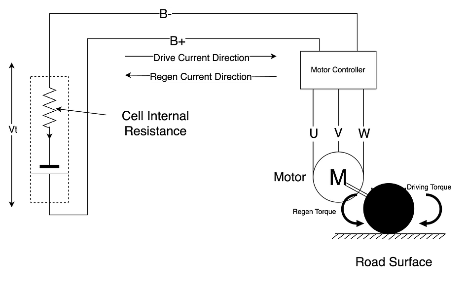
Key equations to consider are:

The first equation signifies the conservation of mechanical to electrical power assuming 100% efficiency, while the second defines the DC bus current flowing back from the motor. By solving these for the terminal voltage Vt, we find:

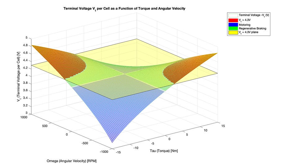
The analysis shows that when in driving mode, where torque (T) and angular velocity (ω) share the same direction, the terminal voltage (Vt) is less than the open-circuit voltage (Voc) based on the State of Charge (SOC). On the other hand, during regenerative mode, where T and ω have opposite directions, Vt exceeds Voc(SOC). The accompanying figure demonstrates how Vt varies with RPM and torque. It’s notable in the regenerative regions that the terminal voltage tends to be higher. For example, setting a terminal voltage limit at 4.3V reveals multiple instances where combinations of regenerative torque and RPMs could surpass this set limit.
Insights on Regenerative Braking in EVs
Our analysis suggests that regenerative current and terminal voltage are contingent on regenerative torque. The higher the torque, the greater the current and terminal voltage. This leads to several design considerations in EVs:
EVs typically have an upper SOC limit, beyond which regenerative braking ceases. This can lead to unexpected experiences, especially on two-wheel vehicles.
High SOCs inherently elevate the cell’s terminal voltage and exceeding specific voltage thresholds can affect battery life, which is a crucial factor in manufacturer warranties. Thus, at high SOCs, regenerative braking is often disabled to prevent overvoltage conditions.
The PMSM Motor
The Permanent Magnet Synchronous Motor (PMSM) is a complex yet versatile component. Contrary to the simplistic view, torque in a PMSM is not directly proportional to the DC bus current. The motor operates along two axes, the D (direct) and Q (quadrature) axes, with the D axis linked to non-torque elements and the Q axis to torque-producing components. The equations governing PMSM operation are as follows:

where:
T — Electromagnetic torque
Idc— DC current
vd — Direct-axis voltage
vq — Quadrature-axis voltage
Is — Total stator current
Vs — Total stator voltage
Rs — Stator resistance
Ld — Direct axis inductance
Lq — Quadrature axis inductance
N — Number of pole pairs
ω — Angular velocity of the rotor (electrical radians per second)
𝛙m — Permanent magnet flux linkage
Vdc — DC link voltage
id — Direct-axis current
iq — Quadrature-axis current
Assuming steady-state conditions ( d id/dt = 0 and d iq/dt = 0 ), and expressing parameters as functions of id and iq, we simplify the equations as shown below:

Regenerative (or Not) Braking via Motor
Delving into the heart of our analysis, we turn our attention to equations for T and Idc . Intriguingly, both equations emerge as quadratic functions in terms of id and iq. This mathematical relationship suggests several key implications:
Independent Control of Idc and T: By manipulating id and iq independently, we theoretically possess the capability to regulate the DC link current. This includes the possibility of achieving a zero DC current, while generating a controlled magnitude of opposing torque.
Adherence to Motor and Controller Limits: It is crucial to ensure that the resultant total phase currents and phase voltages remain within the operational thresholds of both the motor and the controller.
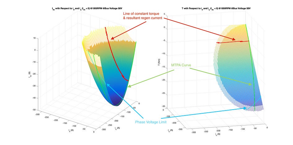
To visualise these concepts, we present a pair of illustrative figures below. It’s important to clarify that the numerical data depicted in these diagrams is not specific to the 450 Apex; rather, they are based on a hypothetical but adequately representative motor model. These graphs demonstrate the relationship between the DC link current (denoted as Idc), the currents id and iq , as well as the generated torque that opposes the direction of rotation (negative torque in cases where the RPM is positive).
Particularly noteworthy is the segment highlighted in red. Here, our objective is to maintain a torque of -4Nm at a mechanical speed of 1000 RPM. The torque plot reveals that multiple id and iq combinations can yield this specific torque value. However, each combination corresponds to a distinct Idc current feeding back to the battery. Interestingly, certain conditions even allow for a scenario where we can either return zero DC current or draw a positive current, all while applying a negative torque.
At a higher mechanical speed of 2000 RPM, the figure in focus below reveals the same -4Nm torque request but under new dynamics. This scenario highlights the role of phase current and voltage limits, which impose additional constraints on the DC link current returning to the battery. These constraints become particularly significant at increased RPMs, emphasising the need for control strategies to balance torque generation with the electrical capabilities the system.
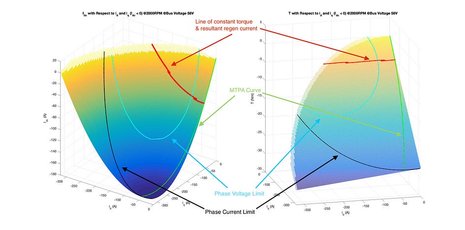
The figure below shows the varying constant torque requests at various RPMs. Note that only the Idc values that lie both within the max phase current limit (boundary defined by black line) and max phase voltage limit (enclosed in the blue line) are achievable in practise.
Energy Dynamics in Braking
In our previous discussions, we delved into the generation of torque that counteracts the rotation of a motor, a process that doesn’t inherently equate to regenerative braking. This raises an intriguing question: What happens to the braking energy? For instance, when decelerating the 450 Apex from 40 km/h to a complete stop using this braking method, the kinetic energy of the vehicle must be conserved and converted into another form of energy. To shed light on this, we present a figure that illustrates what occurs within the inverter during this braking phase.
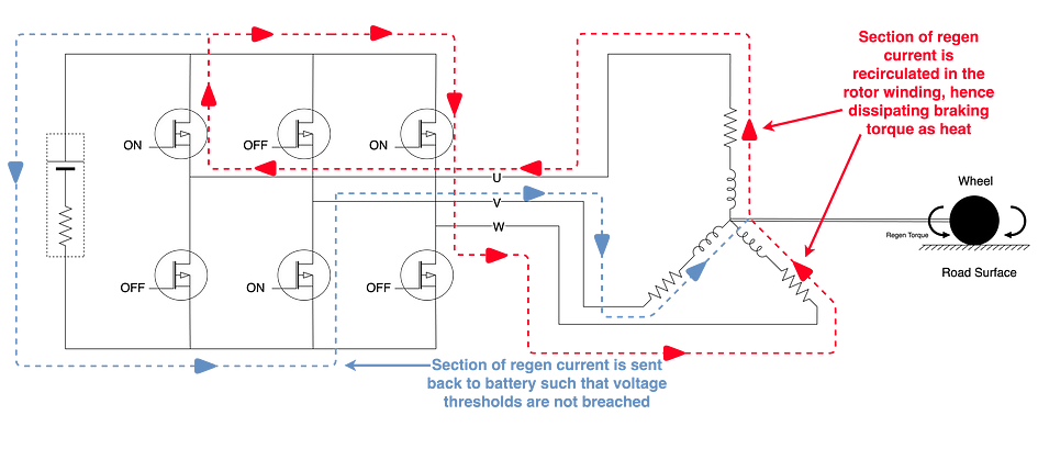
A closer examination of the current produced during braking reveals its division into two distinct components, each subject to independent control:
Regenerative Current Path (Highlighted in Blue): This path channels the current back to the battery, exemplifying conventional regenerative braking.
Stator Recirculation Path (Highlighted in Red): This path involves the recirculation of current within the stator. Termed the “dissipative component,” this current primarily contributes to heating the motor’s stator. Consequently, the energy extracted from braking manifests as an increase in the motor’s temperature, which is then dissipated through conventional cooling methods.
At Ather, we have meticulously tuned the Magic Twist feature to balance effective braking with motor thermal management, ensuring optimal performance even in demanding urban conditions.
Twist & Ride: A Unique Proposition
The Magic Twist feature, which is the subject of multiple IP filings by Ather, aims to enhance the ride experience in the 450 Apex. It offers safe, reliable, and consistent braking, independent of the battery’s state of charge. We invite you to experience this groundbreaking feature soon!
 | A guest post by
|