

Written by Abhishek Chopra
Introduction
In the world of automotive engineering, chassis design presents a unique challenge. The iterative design process, crucial for optimising performance, safety, and manufacturability, is often bogged down by time-consuming analyses. Traditional FEA, while essential for detailed validation, involves complex meshing, contact definitions, and specialised expertise, creating a bottleneck. Similarly, traditional formability analysis often involves a separate handoff to manufacturing engineers, adding further delays. This slows down the design process and limits the number of design iterations a chassis engineer can explore. The solution? Empowering design engineers to conduct basic simulations themselves, right at the design stage.
Currently, design engineers often rely heavily on the manufacturing team formability analysis, leading to queues and slowing down the design process. Each design change requires a new setup and solution, adding significant time. Formability analysis often involves creating physical prototypes or waiting for manufacturing to evaluate the design, further extending the cycle. This dependency not only delays the design process but also ties up valuable manufacturing resources.
The proposed solution involves integrating user-friendly forming simulation tools directly into the design engineer's workflow. These tools enable engineers to perform basic forming simulations, with significantly less complexity and time investment. This shift empowers engineers to quickly evaluate multiple design concepts, gaining directional insights into performance, productivity and manufacturability early in the process.
The Power of Design-End Simulation for Manufacturability (Forming):
Sheet metal forming simulations are a powerful tool for design engineers, offering valuable insights into the manufacturability of their designs early in the development process. By simulating the forming process virtually, engineers can identify potential issues and optimise their designs before any physical prototypes are created. This saves time, reduces costs, and leads to more robust and efficient designs.
Process Flow of a Typical Sheet Metal Forming(Draw and Deep Draw) Simulation:
Import Geometry: The first step is to import the CAD model of the part into the forming simulation software. This could be the design of a single part or a complete assembly.
Define Material Properties: Accurate material properties are crucial for reliable simulation results. This includes parameters like Young's modulus, Poisson's ratio, yield strength, rBAR, elongation and plastic behaviour (e.g., hardening curve).
Set Up the Forming Process: This involves defining the forming process parameters, such as:
Blank Size and Shape: The initial shape and dimensions of the sheet metal blank.
Die Design: The geometry of the dies used to form the part.
Press and Binder Forces: The forces applied by the press and binder during forming.
Friction: The friction between the sheet metal and the dies.
Drawbeads: The presence and location of drawbeads, which control material flow during forming.
Meshing: The software automatically generates a mesh of the blank, which is used to solve the simulation. The mesh density and type can be adjusted based on the complexity of the part and the desired accuracy.
Run the Simulation: Once the setup is complete, the simulation is run. The software calculates the stresses, strains, and material flow during the forming process.
Analyse Results: After the simulation, engineers can analyse the results to gain insights into the formability of the design. This includes visualising:
Thickness Distribution: Identify areas of thinning or thickening, which can indicate potential failure points or wrinkles.
Strain Distribution: Analyse the strain levels in the material, which can help predict cracking or necking.
Stress Distribution: Understand the stress distribution in the formed part, which can help optimise the design for strength and durability.
Formability Limits: Determine if the material is being stretched beyond its formability limits, which can lead to splitting or tearing.
Springback: Predict the amount of springback (elastic recovery) after forming, which can affect the final shape and dimensions of the part.
Optimise the Design: Based on the simulation results, engineers can modify the design to improve formability. This could involve:
Adjusting Part Geometry: Modifying the shape of the part to reduce stress concentrations or improve material flow.
Changing Blank Size and Shape: Optimising the blank size and shape to ensure adequate material for forming.
Modifying Die Design: Adjusting the die design to improve material flow and reduce the risk of defects.
Adding Drawbeads: Strategically placing drawbeads to control material flow and prevent wrinkles.
Insights from Sheet Metal Forming Simulations:
Early Defect Detection: Identify potential forming defects like thinning, cracking, wrinkling, and springback early in the design stage.
Reduced Lead Times: Reduce the number of physical prototypes and design iterations, leading to shorter lead times.
Cost Savings: Avoid costly rework and tooling modifications by identifying and addressing formability issues early on.
Improved Product Quality: Optimise designs for manufacturability, leading to higher quality and more robust products.
Increased Design Confidence: Gain confidence in the manufacturability of the design before committing to tooling and production.
By identifying these issues early, the design engineer can modify the design to improve formability before involving the manufacturing team. This saves significant time and reduces iterations.
Let’s understand the above using a simple case study of a bracket:
Initial Design and Analysis (Iteration 1)
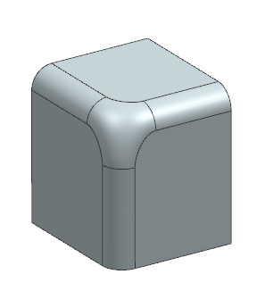
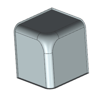
The initial bracket design, featuring a corner fillet, was subjected to forming simulation software to assess thinning, formability, and FLD (Forming Limit Diagram).
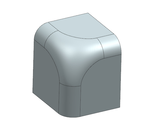
FIG 1 and FIG 1A illustrate the initial bracket design.
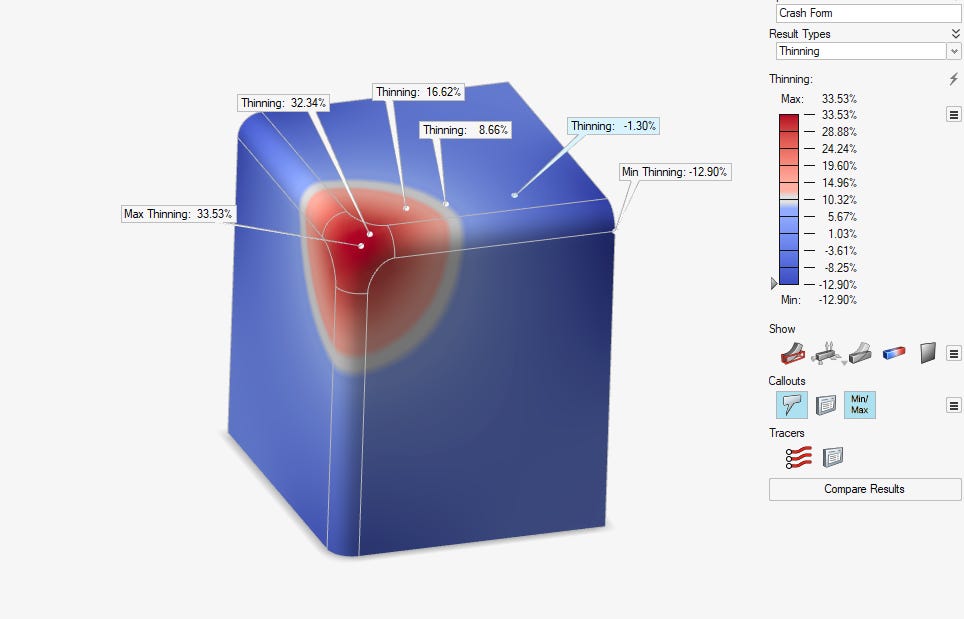
FIG 2 presents the thinning analysis results, highlighting a maximum thinning of 33.53% at the corner, which surpasses the acceptable limit of 20%. This excessive thinning indicates a high risk of material failure during the forming process.
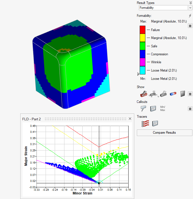
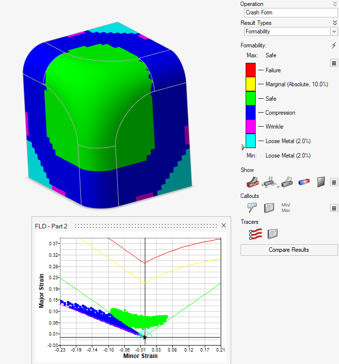
FIG 3 depicts the formability and FLD results, revealing a marginal area around the blend that could potentially lead to tearing or wrinkling.
Design Modification and Re-analysis (Iteration 2)
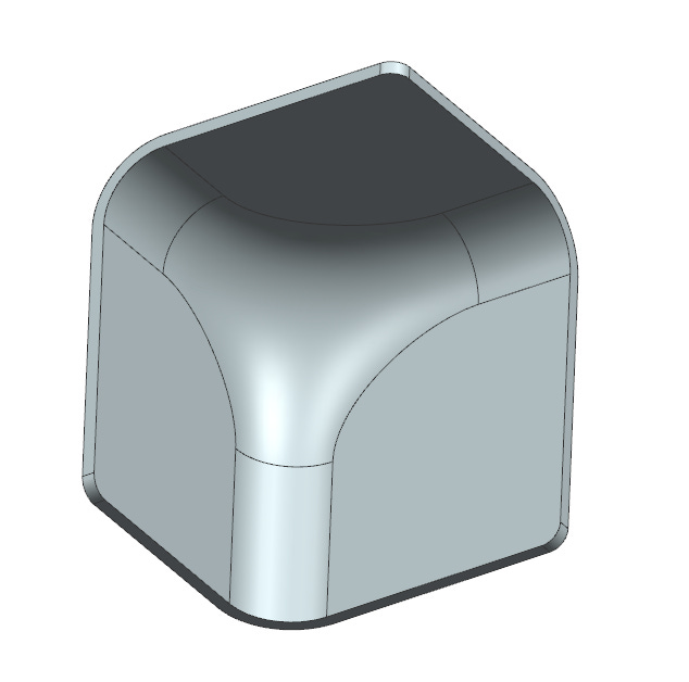
Based on the initial analysis results, the corner blend of the bracket was modified (FIG 4 and FIG 4A) and the forming analysis was repeated. The modification aimed to reduce stress concentration and improve material flow in the critical corner region.
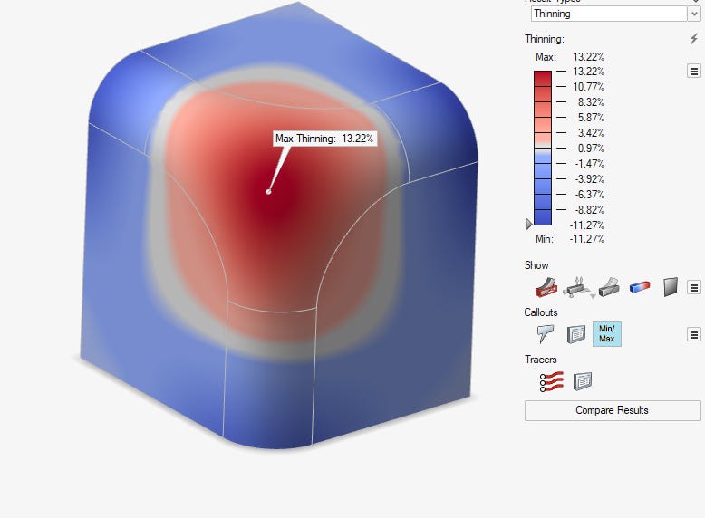
FIG 5 displays the thinning analysis results for the modified design, showing a maximum thinning of 13.22% at the corner, which falls within the acceptable range. This indicates that the risk of material failure due to thinning has been mitigated.
FIG 6 presents the formability and FLD results for the modified design, demonstrating that the formability has been improved and the design is now safe for forming without defects such as tearing or wrinkling.
Benefits and Implications for Design Engineers
While this case study focused on a specific bracket design, the principles and methodologies applied can be extended to a wide range of sheet metal components. Design engineers can leverage forming simulation software to:
Evaluate different design alternatives and select the most formable option.
Optimise material utilisation and reduce scrap.
Predict potential defects and implement preventive measures.
Improve communication and collaboration with manufacturing engineers.
Key Concepts in Deep Drawing
Deep Drawing: A sheet metal forming process where a sheet metal blank is drawn into a forming die by a punch. It is widely used in industries like automotive for creating complex shapes.
Draw Force: The force required by the punch to deform and draw the sheet metal into the die.
Blank Holder Force (BHF): The force applied by the blank holder to hold the sheet metal blank in place during the drawing process. Its primary function is to prevent wrinkling of the flange (the portion of the blank that remains outside the die).
Relationship Between Draw Force and Blank Holder Force
The relationship between draw force and blank holder force is complex and influenced by factors like material properties, sheet thickness, lubrication, die and punch geometry, and friction.
Generally, too little BHF can lead to wrinkling, while too much BHF can increase friction, leading to thinning and potential tearing of the sheet metal.
Therefore, an optimal BHF is essential.
There is no simple universal equation to define the relationship, as it is highly dependent on the specific deep drawing operation.
Based on trials, the blank holder force is often expressed as a percentage of the draw force. Common practice has shown that the blank holder force is often around 20% to 30% of the draw force. However, this percentage can vary greatly.
Modern research is focused on variable blank holder force, to optimise the force during different stages of the draw.
Key Considerations
Optimisation of BHF is crucial for defect-free deep drawing.
Finite element method (FEM) simulations are increasingly used to predict and optimise the relationship between draw force and BHF.
Variable BHF strategies are being developed to improve forming quality.
In essence, the relationship is about finding a balance: enough BHF to prevent wrinkling, but not so much that it causes tearing.
Understanding Press and Binder Forces
Determining the press and binder forces in a sheet metal forming component is crucial for a successful forming process.
Press Force: The force applied by the press to the punch, which then transfers the force to the sheet metal blank. It's the primary force responsible for deforming the material and shaping it into the die cavity.
Binder Force: The force applied by the binder to the sheet metal blank, holding it in place and controlling its flow into the die cavity. It helps prevent wrinkles and ensures proper material distribution during forming.
Factors Influencing Press and Binder Forces
Several factors influence the required press and binder forces, including material properties, part geometry, die design, friction, and lubrication.
Simplified Force Estimation
A simplified approach to estimating the bending force (P) in sheet metal bending uses the following formula:
P = (K * L * T^2) / V + FOS
Where:
K: Material coefficient (generally between 1.3 and 1.5 depending on the material type)
L: Bending length (length of the bend line)
T: Sheet thickness
V: Lower die width (width of the V-groove)
This formula provides a basic estimate for air bending with a V-die. However, it doesn't account for factors like die angle, friction, and material hardening.
Drawing Force Estimation
For deep drawing operations, the maximum drawing force (P) can be estimated using:
P = k * t * d * Y
Where:
k: Factor approximately equal to (D/d - 0.6)
t: Material thickness
d: Outside diameter of the drawn cup
Y: Yield strength of the material
D: Blank diameter
This formula provides a rough estimate for drawing cylindrical cups. It doesn't account for factors like blankholder force, friction, and draw-bead effects.
Blankholder Force
The blankholder force is crucial for controlling material flow during drawing. It's typically a percentage of the drawing force and can be estimated using:
Blankholder Force = Fbh * Drawing Force
Where Fbh is the blankholder force factor, typically ranging from 0.20 to 0.30 (20% to 30% of the drawing force).
Limitations of Simplified Formulas
These simplified formulas provide a starting point for estimating forces, but they have limitations:
Accuracy: They often oversimplify the process and may not be accurate for complex geometries, materials, and forming operations.
Process Specifics: They don't account for all process parameters, such as friction, lubrication, die design, and material properties like strain hardening.
Accuracy of Forming Simulation:
While design-end forming simulations provide valuable directional insights into formability and can accurately predict the location of potential defects, it's important to understand that these are design-level simulations. They may not capture the same level of detail as specialised forming simulation software used by manufacturing engineers. The accuracy depends on several factors, including geometry complexity, material properties, and forming parameters. However, for initial design exploration and identifying potential problem areas, these tools are invaluable. They allow design engineers to make informed decisions about formability early, reducing the risk of manufacturing issues later.
Correlation and Validation:
While design-end simulations provide valuable directional insights, they don't replace the need for detailed analyses by specialised teams. A crucial step is correlating the results obtained from these simplified simulations with the results from more comprehensive manufacturing simulations.
Conclusion
Integrating user-friendly simulation tools early in the design process can significantly enhance efficiency and minimise bottlenecks. By enabling engineers to visualise and analyse structures and manufacturing processes, these tools foster a deeper understanding of the design's implications. This early insight allows for prompt design optimisation, faster iteration, and more effective allocation of specialised resources. For instance, potential structural weaknesses can be identified and addressed before they become costly problems, and manufacturing challenges can be anticipated and mitigated. This proactive approach streamlines the development process, reducing the need for extensive rework and delays. While detailed analyses remain essential for final validation, incorporating simulation early represents a paradigm shift towards a more agile and efficient workflow, ultimately leading to improved product quality, faster time-to-market, and reduced development costs.
 | A guest post by
|